
The exponential growth of the Internet in the last 30 years exposed shortcomings in the original IP protocol design. As the internet began to rapidly expand from its initial military network research status into commercial prominence, the demand for IP addresses (particularly in the class B space) skyrocketed.
Experts started to worry about the long-term scaling properties of classes A, B, and C IP address scheme, and began considering ways to modify IP assignment policy and routing protocols to accommodate the growth.
This led to the establishment of the Routing and Addressing (ROAD) group by the Internet Engineering Task Force (IETF) in the early 1990s to work out ways of restructuring the IP address space to increase its lifespan.
The group according to IETF RFC 4632 identified three major problems:
- Exhaustion of the Class B network address space
- Growth in internet routers’ routing tables beyond the capacity of current hardware and software.
- Eventual exhaustion of the 32-bit IPv4 network address space
As a short to mid-term measure, the ROAD group proposed a solution to allow the use of “classless” IP assignment systems to slow the growth of global routing tables and to reduce the rate of consumption of IPv4 address space. This eventually gave birth to what we now know as Classless Inter-Domain Routing (CIDR), and Variable Length Subnet Mask (VLSM), which allows greater flexibility in the creation of sub-networks, overcoming the strict rules of the A, B, and C classes. In this guide, we’re going to help you understand the concept of VLSM, and show you how to implement VLSM Subnetting.
VLSM Fundamentals
In order to fully grasp the concept of VLSM, we first need to understand the term subnet mask, subnetting, and Supernetting.
Subnet Mask
Subnet masks are used by a computer to determine if any computer is on the same network or on a different network. An IPv4 subnet mask is a 32-bit sequence of ones (1) followed by a block of zeros (0). The ones designate the network prefix, while the trailing block of zeros designates the host identifier. In shorthand, we use /24, which simply means that a subnet mask has 24 ones, and the rest are zeros.
Binary Notation | Decimal Notation | |
|---|---|---|
IP address | 11000000.00000000.00000010.10000010 | 192.0.2.130 |
Subnet mask | 11111111.11111111.11111111.00000000 | 255.255.255.0 |
Table 1.0 IP address and subnet mask in binary and decimal format
Subnetting vs Supernetting
Subnetting and supernetting are techniques used to manage IP address allocation and improve network organization.
Subnetting divides a larger network into smaller, more manageable subnetworks (subnets). This is done by borrowing bits from the host portion of the IP address to create additional network bits. Subnetting improves network performance and security by limiting broadcast traffic to smaller subnets and organizing network segments more effectively. For example, a network with the address 192.168.1.0/24 could be subnetted into smaller networks, such as 192.168.1.0/26, 192.168.1.64/26, etc., making it easier to control traffic and allocate IP addresses efficiently.
Supernetting, on the other hand, combines multiple networks into a larger network by borrowing bits from the network portion of the address. This results in a single, broader address range. Supernetting is often used by Internet Service Providers (ISPs) to aggregate IP addresses, simplifying routing tables and improving scalability. For instance, the networks 192.168.0.0/24 and 192.168.1.0/24 can be supernetted into 192.168.0.0/23.
Differences and Benefits:
- Subnetting improves network security, traffic management, and allows better utilization of IP addresses in smaller environments.
- Supernetting helps with efficient routing, reduces the size of routing tables, and allows scalability for large networks or ISPs.
In summary, subnetting focuses on breaking down large networks, while supernetting combines smaller networks for better management.

Approaches to Subnetting: FLSM vs. VLSM
There are two approaches to subnetting an IP address for a network: Fixed length subnet mask (FLSM) and variable-length subnet mask (VLSM). In FLSM subnetting, all subnets are of equal size with an equal number of host identifiers. You use the same subnet mask for each subnet, and all the subnets have the same number of addresses in them. It tends to be the most wasteful because it uses more IP addresses than are necessary.
Advantages of VLSM
VLSM is a subnet design strategy that allows all subnet masks to have variable sizes. In VLSM subnetting, network administrators can divide an IP address space into subnets of different sizes, and allocate it according to the individual need on a network. This type of subnetting makes more efficient use of a given IP address range. VLSM is the defacto standard for how every network is designed today. Table 2.0 below is a summary of the differences between FLSM and VLSM Subnetting. VLSM is supported by the following protocols: Open Shortest Path First (OSPF), Enhanced Interior Gateway Router Protocol (EIGRP), Border Gateway Protocol (BGP), Routing Information Protocol (RIP) version 2 and 3, and Intermediate System-to-Intermediate System (IS-IS). You need to configure your router for VLSM with one of those protocols.
FLSM (Fixed Length Subnet Masks) Subnetting | VLSM (Variable Length Subnet Masks) Subnetting |
|---|---|
Old-fashioned | Modern |
Subnets are equal in size | Subnets are variable in size. |
Subnets have an equal number of hosts | Subnets have a variable number of hosts |
Supports both classful and classless routing protocols | Supports only classless routing protocols |
Wastes more IP addresses | Wastes fewer IP addresses |
Subnets use the same subnet mask | Subnets use different subnet masks |
Simple configuration and administration | Complex configuration and administration |
Table 2.0 Differences between FLSM and VLSM Subnetting
Practical Scenarios and Decision Making
Now imagine this scenario: John has just been hired as a network administrator for a new company with six departments. He’s expected to create six separate subnets, one for each department. He was given a class A 10.0.0.0 private network address for this purpose; and so from all indications, he obviously has a lot of IP address space and can’t even come close to imagining that he’d ever run out of IP addresses. For this reason, John has been wondering why he should bother with the VLSM design process. Should he use a VLSM or an FLSM network design? Well, the answer is simple. By creating contiguous blocks of valid addresses to specific areas of the network, he can then easily summarize the network and keep route updates with a routing protocol to a minimum. Why would anyone want to advertise several networks between buildings when you can just send one summary route between buildings and achieve the same result?
Implications of Wastage in Addressing
Besides, wasting of public network IP addressing space has both technical and economic implications. On the technical side, it accelerates its exhaustion; and on the economic side, it costs a lot of money because public network IP addresses are expensive. Therefore, the introduction of VLSM allowed the IP address allocation of a smaller block.
Implementing VLSM Subnetting
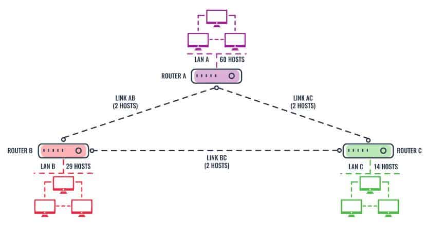
We will begin this section by attempting to solve a practical VLSM problem. Now, imagine you were recently hired as a Network Engineer for Braxton Investment Limited. Using the VLSM technique, design an IP plan for the company with an IP range of 192.168.4.0/24. The company’s network consists of three local area networks: LAN A, LAN B, and LAN C as shown in Figure 2.0 below. These three LANs are connected with three serial links: Link AB, Link BC, and Link AC.
One of the easiest ways to solve VLSM problems is by using a subnetting chart like the one shown in Table 3.0 below. We will use this chart to tackle the above problem
Subnet | 1 | 2 | 4 | 8 | 16 | 32 | 64 | 128 | 256 |
Host | 256 | 128 | 64 | 32 | 16 | 8 | 4 | 2 | 1 |
Subnet Mask | /24 | /25 | /26 | /27 | /28 | /29 | /30 | /31 | /32 |
Table 3.0 VLSM subnetting chart
As you can see from the diagram, we have six networks LAN A, LAN B, LAN C, and link A, link B and a link C. Links A, B, and C are also three separate networks and each requires two host identifiers. Thus our task is to design an IP plan for each of the six networks according to their stipulated sizes using VLSM subnetting method. We need five steps to solve the problem:
Step 1: Arrange the networks from the largest to the smallest as shown in Table 4.0 below:
LAN Name | No of Host |
|---|---|
LAN A | 60 |
LAN B | 29 |
LAN C | 14 |
Link AB | 2 |
Link AC | 2 |
Link BC | 2 |
Table 4.0 LAN arranged according to the number of hosts
Step 2: Implement VLSM subnetting for the largest network (LAN A)
The largest network LAN A requires 60 hosts. From the Host section (row) of our subnetting chart below, the closest to the required 60 hosts is 64, which corresponds to 4 subnets and a new CIDR value of /26 (the column is in bold). From this relevant information, we will build a new table containing Network ID, Subnet Mask in CIDR notation, Usable, and Name of Local Area Network affected. Keep in mind the first host identifier is reserved for the network ID and the last host ID is reserved for the broadcast ID, so the total number of usable host IDs for each subnet in this particular case is 62 (64-2).
Subnet | 1 | 2 | 4 | 8 | 16 | 32 | 64 | 128 | 256 |
Host | 256 | 128 | 64 | 32 | 16 | 8 | 4 | 2 | 1 |
Subnet Mask | /24 | /25 | /26 | /27 | /28 | /29 | /30 | /31 | /32 |
Given the IP range: 192.168.4.0/24
Network ID | Subnet Mask | Total Host | Usable Host Range | Name of LAN |
|---|---|---|---|---|
192.168.4.0 | /26 | 64 | 192.168.4.1–192.168.4.62 | LAN A |
192.168.4.64 | /26 | 64 | Unassigned |
|
192.168.4.128 | /26 | 64 | Unassigned |
|
192.168.4.192 | /26 | 64 | Unassigned |
Table 5.0 IP plan for LAN A (60 hosts)
Now let’s list a network ID for each subnet. Keep in mind that only the fourth octet changes; the first three octets remain the same:
- The first network ID is always the original given ID which is 192.168.4.0
- The second network ID is 192.168.4.64
- The third network ID is 192.168.4.128
- The fourth network ID is 192.168.4.192
Here is the pattern: The first network ID is always the original one. The next network ID is obtained by adding 64 to the previous one. We can assign any of these for subnets to LAN A since they are all equal in size, but for the sake of simplicity, we assign the first subnet (192.168.4.0) to LAN A. The other three available subnets can be marked as unassigned and reserved for future use. We have completed the task of designing the IP plan for the largest LAN – LAN B.
Step 3: Implement VLSM subnetting for the second-largest network (LAN B)
The second-largest network, LAN B, requires 29 hosts. The minimum number of hosts which can satisfy LAN B with the 29 hosts on our subnetting chart is 32. This corresponds to eight subnets and a new CIDR value of /27 (the column is in bold).
Now select the first unassigned large subnet in Table 5.0 above and subdivide into two smaller subnets. This gives us 192.168.4.64 and 192.168.4.96 marked in green in Table 6.0 below. Again the pattern is simple: The first network ID is always the original one. The next network ID is obtained by adding 32 to the previous one. We can then assign 192.168.4.64 to LAN B, and mark the second one (192.168.4.96) as unassigned and reserved for future use. We have completed designing the IP plan for LAN A.
Subnet | 1 | 2 | 4 | 8 | 16 | 32 | 64 | 128 | 256 |
Host | 256 | 128 | 64 | 32 | 16 | 8 | 4 | 2 | 1 |
Subnet Mask | /24 | /25 | /26 | /27 | /28 | /29 | /30 | /31 | /32 |
Network ID | Subnet Mask | Total Host | Usable Host Range | Name of LAN |
|---|---|---|---|---|
192.168.4.64 | /27 | 32 | 192.168.4.65 – 192.168.4.94 | LAN B |
192.168.4.96 | /27 | 32 | Unassigned |
Table 6.0 IP plan for LAN B (29 hosts)
Step 4: Implement VLSM subnetting for LAN C
This step repeats the process above. The minimum number of hosts which can satisfy LAN C with the 14 hosts on our subnetting chart is 16. This corresponds to 16 subnets and a new CIDR value of /28 (the column is in bold).
Now select the first unassigned subnet in Table 6.0 above and subdivide into two smaller subnets. This gives us 192.168.4.96 and 192.168.4.112 in Table 7.0 below. Again the pattern is simple: The first network ID is always the original one. The next network ID is obtained by adding 16 to the previous one. We can then assign 192.168.4.96 to LAN C, and mark the second one (192.168.4.112) as unassigned and reserved for future use. We have completed designing the IP plan for LAN C.
Subnet | 1 | 2 | 4 | 8 | 16 | 32 | 64 | 128 | 256 |
Host | 256 | 128 | 64 | 32 | 16 | 8 | 4 | 2 | 1 |
Subnet Mask | /24 | /25 | /26 | /27 | /28 | /29 | /30 | /31 | /32 |
Network ID | Subnet Mask | Total Host | Usable Host Range | Name of LAN |
|---|---|---|---|---|
192.168.4.96 | /28 | 16 | 192.168.4.97– 192.168.4.110 | LAN C |
192.168.4.112 | /28 | 16 | Unassigned |
Table 7.0 IP plan for LAN C (14 hosts)
Step 5: Implement VLSM subnetting for Link A, B, and C
The last step is to assign three smaller subnets for serial links A, B, and C. Each link requires two host IDs. Therefore, the minimum number of hosts which can each link with two hosts on our subnetting chart is four. This corresponds to 64 subnets and a new CIDR value of /30 in our subnetting chart (the column is in bold).
Now select the unassigned subnet in Table 7.0 above and subdivide into four smaller subnets to accommodate the subnets for the three serial links. This gives us four unique IPs as shown in Table 8.0 below.
Subnet | 1 | 2 | 4 | 8 | 16 | 32 | 64 | 128 | 256 |
Host | 256 | 128 | 64 | 32 | 16 | 8 | 4 | 2 | 1 |
Subnet Mask | /24 | /25 | /26 | /27 | /28 | /29 | /30 | /31 | /32 |
Network ID | Subnet Mask | Total Host | Usable Host Range | Name of LAN |
|---|---|---|---|---|
192.168.4.112 | /30 | 4 | 192.168.4.113–192.168.4.114 | LINK AB |
192.168.4.116 | /30 | 4 | 192.168.4.117–192.168.4.118 | LINK AC |
192.168.4.120 | /30 | 4 | 192.168.4.121–192.168.4.122 | LINK BC |
192.168.4.124 | /30 | 4 | Unassigned |
Table 8.0 IP plan for Link A, B, and C (2 hosts each)
Again here’s the pattern: The first network ID is always the original one. The next network ID is obtained by adding four to the previous one. We can then assign the first three IPs to Link A, B, and C respectively, and mark the last one (192.168.4.124) as unassigned and reserved for future use. We have completed designing the IP plan for Link A, B, and C, and indeed the entire network. The table below is the complete IP plan for Braxton Investment Limited.
Network ID | Subnet Mask | Total Host | Usable Host Range | Name of LAN |
|---|---|---|---|---|
192.168.4.0 | /26 | 64 | 192.168.4.1–192.168.4.62 | LAN A |
192.168.4.64 | /27 | 32 | 192.168.4.65 – 192.168.4.94 | LAN B |
192.168.4.96 | /28 | 16 | 192.168.4.97– 192.168.4.110 | LAN C |
192.168.4.112 | /30 | 4 | 192.168.4.113–192.168.4.114 | LINK AB |
192.168.4.116 | /30 | 4 | 192.168.4.117–192.168.4.118 | LINK AC |
192.168.4.120 | /30 | 4 | 192.168.4.121–192.168.4.122 | LINK BC |
Table 9.0 IP plan for Braxton Investment limited
VLSM is a crucial technique in modern network design. If you want to design and implement scalable and efficient networks, you should definitely master the art of VLSM subnetting. One of the key objectives of VLSM subnetting in IPv4 is to improve efficiency in the utilization of the space available. This has managed to keep it going in the last 30 years. But on the 25th of November 2019, RIPE Network Coordination Centre announced that it made the final /22 IPv4 address allocation, and has officially run out of IPv4 addresses. A longer-term solution to the eventual exhaustion of the 32-bit IPv4 network address space is the 64-bit IPv6 protocol.
VLSM Subnetting FAQs
What is VLSM with example?
VLSM (Variable Length Subnet Mask) is a technique that allows network administrators to divide an IP address space into subnets of different sizes, rather than dividing it into subnets of the same size. This allows for more efficient use of IP addresses, as smaller subnets can be used for smaller networks, and larger subnets can be used for larger networks.
For example, if a network administrator is given a Class C IP address space of 192.168.1.0/24, they can use VLSM to divide it into two subnets: one with a /25 mask for a smaller network, and one with a /26 mask for a larger network. The smaller network would have 128 host addresses, and the larger network would have 64 host addresses.
This allows the administrator to assign IP addresses more efficiently, as they can use the larger subnet for a network that needs more IP addresses and the smaller subnet for a network that needs fewer IP addresses.
What does it mean when it says "IP not in subnet range"?
“IP not in subnet range” simply means that you are attempting to use an IP address that doesn’t belong to the block of IP’s defined by the subnet mask in question. Based on our VLSM example above, if the network address and subnet mask for LAN B is 192.168.4.0 and 255.255.255.192 (/26) respectively, and you are trying to use an ip address of 192.168.2.2 then you will get an “ip not in subnet range” error. The only usable host IP addresses in range are 192.168.4.1–192.168.4.62 as shown on Table 9.0.
How do you calculate VSLM?
The simplest way to calculate VLSM is by using a subnetting chart like the one shown in Table 3.0 above, and then following the steps below:
- Arrange the requirements of IP addresses in descending order like the one shown on Table 4.0 above
- Using the subnetting chart, assign the appropriate subnet masks to each subnet based on the required number of hosts.
- Allocate one the resulting subnets to the designated LAN and reserve the rest for future use
- Pick the next available subnet from step 3 above, and repeat the subnetting process using the chart till you get to last network on your list
- Review and document your subnetting summary
Please see the “Implementing VLSM Subnetting” section above for detailed explanation.
How would the use of VLSM impact your choice of routing protocols?
Well, the bad news is that not all routing protocols support VLSM. Classful routing protocols such as RIPv1 and IGRP, do not support VLSM. Therefore, it’s important to ensure that you configure your router for VLSM with one of the supported protocols. But the good news is that all current generation of routing protocols such as RIPv2/v3, OSPF, IS-IS, EIGRP, BGP, and even Static routes, are classless and therefore support VLSM.
What are the 5 classes in subnetting?
In IP addressing, there are five classes of IP addresses: A, B, C, D, and E.
- Class A addresses have a default mask of 255.0.0.0 and a range of 1.0.0.0 to 127.255.255.255. The first octet is used for the network address and the remaining three octets are used for the host address.
- Class B addresses have a default mask of 255.255.0.0 and a range of 128.0.0.0 to 191.255.255.255. The first two octets are used for the network address and the remaining two octets are used for the host address.
- Class C addresses have a default mask of 255.255.255.0 and a range of 192.0.0.0 to 223.255.255.255. The first three octets are used for the network address and the last octet is used for the host address.
- Class D addresses are reserved for multicast groups and have a range of 224.0.0.0 to 239.255.255.255
- Class E addresses are reserved for experimental or future use and have a range of 240.0.0.0 to 254.255.255.255
Note that, nowadays Class A,B,C are mostly used for subnetting, class D and E are not used for subnetting
Why is a connection between two routers considered to be a subnet?
The link between two routers is a small network by itself and so it can be included in the wider network as a subnet. Imagine that the network is a WAN, in which case, the link between two routers could be across the internet. Both routers would need an internet-facing IP address. Within the private network, this still holds true; it is a network with two hosts and becomes a subnet with two hosts.
Aren’t the router interfaces included as part of their respective subnets?
IP addresses on a router are assigned to the interface and not to the entire device. Thus, it will have a different IP address for each subnet in which it is included.

 Tutorial)
Thank you for the thorough explanation about VLSM and this helps me understand on how VLSM work, practical and simple.
Hi there,
First of all, thanks for the extremely thorough explanation, very detailed and straight to the point. Loved it.
I just want to know if it’s possible to make another one talking about VLSM subnetting if we aim to maximize network size and minimize IP addresses waste. Thanks in advance !
OK. Thanks a lot…, but anyway I have question: What if I plan allocate range first for the largest 60 hosts i.e. 192.168.4.0-192.168.4.63 with subnet mask /26 (Valid Host addresses 192.168.4.1-192.168.4.62), Next we allocate 14 hosts i.e. 192.168.4.64-192.168.4.79 with subnet mask /28 (Valid Host Addresses 192.168.4.65-192.168.4.78), and Next allocate 29 hosts i.e. 192.168.4.80-192.168.4.111 with subnet mask /27 (Valid Host Addresses 192.168.4.81-192.168.4.110), and the next rest possible addresses for Point-to-Point Links: 192.168.4.112-192.168.4.115 (VHAs: 192.168.4.113 & 192.168.4.114), next 192.168.4.116-192.168.4.119 (VHAs: 192.168.4.117 & 192.168.4.118), next third and last PtP links: 192.168.4.120-192.168.4.123 (VHAs: 192.168.4.121 & 192.168.4.122). In Cisco Packet Tracer & GNS3 there are overlaping subnets…
Could explain why…???
First time I seen serial links as a subnet. Can you explain this please? Aren’t the router interfaces included as part of their respective subnets A, B and C?
Thanks. This is great.
What to do, when let’s say one already assigned 14 host in LAN C and there’s a need for 3 more (new hires for instance)?
Create another 14 host subnet for them? Thanks
The scenario you described rarely occurs in real life because network engineers usually sit down to design IP addressing plan that meets the immediate and long term needs of the organization. So if there’s need for additional 3 hosts in LAN C, that means the minimum number of hosts required for LAN C is now 17. To satisfy LAN C requirements, you need to create a fresh 17 host (minimum) subnet and reassign IPs to everyone on that LAN. This corresponds to CIDR value of /27 in our chart.
Thanks you very much, I see my broblem.
This is one of the most thorough and easy to follow guides for subnetting that I’ve stumbled upon. This will be extremely helpful for my CCNA course, thank you
Thank you so much for this article. I was struggling to find Network ID’s for different LAN’s.
Even though there are many artifacts on internet that explains the concept of VLSM , but not like this post which makes it so simple with a solved example. In order not to loose it , I copied and added this explanation to my learning notes. Keep up the good work of sharing this with the community. Just one question.. what happens to the unassigned Network ID’s under each Subnet mask option ?
Nothing really. You keep them for future use as the need arises.
this helped me to understand the vlsm thank you very much
According to the diagram, shouldn’t LAN A require 60 hosts, LAN B require 29 hosts, and LAN C require 14 hosts?
Well spotted Norm. We have updated the post. Thank you!
Very nice and simple explanation, it would be great if you can add real hands on configuration of an OSPF router like ciscos , a practice, thanks again for making this available for the community
We are happy to have people use our materials as long they link or attribute to us. I hope this helps.