In networking, different types of cables are used to facilitate communication between devices, each serving a specific purpose depending on the devices being connected and the network setup. Cable types can generally be categorized based on their internal wiring configuration and intended use. The primary function of each type of cable is to ensure the correct transmission of data by aligning the correct signal pathways between two or more devices.
Some cables are designed for connecting devices of different types, such as a computer to a switch or a router, while others are used for connecting similar devices, such as two switches or two computers. The wiring in these cables determines the paths through which the electrical signals travel, with certain configurations required to “cross” or “straighten” the signals for proper communication.
There are also cables that facilitate console connections, used for managing and configuring network devices like routers and switches. These specialized cables typically use a different wiring scheme to ensure that signals are transmitted correctly for tasks like system setup or troubleshooting.
By understanding the various cable types and their functions, you can ensure proper connectivity and performance in your network. In this article, we’ll explore the differences between these cables, helping you choose the right one for your specific network configuration needs.
Cable Types
The most common form of network cable is called “unshielded twisted pair” (UTP). This cable format is used for the Ethernet wiring standards, which are managed by the Institute of Electrical and Electronics Engineers (IEEE). These wiring standards are referred to by the code 802.3. The Ethernet standards are open to anyone to read and they include specifications of cable configurations and the types of connectors used to plug cables into devices. What we conventionally know as a network cable is an 802.3 specified cable for Ethernet networks.
Straight through, crossover, and rollover cable differences
The distinction between a straight through, crossover, and rollover cable comes down to the way that the connectors on each end are wired. A UTP cable contains eight wires. Each individual wire is covered in a colored wire plastic coating and the entire bundle is encased in an outer shell.
In the twisted pair configuration, the eight wires within the cable are split up into four pairs. The two wires in a pair are twisted around each other. This treatment protects both wires from interference. The pairing is easy to spot because one of the two is encased in a coating of solid color while the other is white with a spiral stripe in the pair’s color. This pair’s colors are:
- Green
- Orange
- Blue
- Brown
Cable connectors
The conventional name for the connectors on the ends of Ethernet cables is RJ-45. This is not the proper name however, as the RJ-45 is a discontinued format of telephone wire connector. The proper name for these connectors, according to the 802.3 wiring standards is “8P8C“, which stands for “eight positions, eight connectors.” However, don’t make a fuss if you hear a network technician call the connector an RJ-45. This is the way everyone names these plugs and if you make a big thing about it, you’ll be sitting by yourself in the break room at lunchtime.
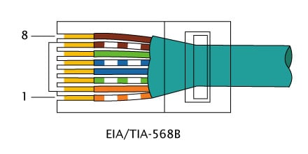
There is a standard sequence for those colored wires in an 8P8C connector. It is not entirely logical. The order is as follows:
- Pin 1: Orange stripe
- Pin 2: Orange solid
- Pin 3: Green stripe
- Pin 4: Blue solid
- Pin 5: Blue stripe
- Pin 6: Green solid
- Pin 7: Brown stripe
- Pin 8: Brown solid
It doesn’t really make sense that all of the pairs go into the connector next to each other except for the green pair and there is no real reason why the blue stripe/solid order is reversed. However, this is the wiring standard and you have to follow it because the socket the connector plugs into is wired internally to accept the signals carried by the color-coded wires in this specific order.
The connector layout listed above is specified in the standard EIA-568B.This was defined by the Electronic Industries Alliance, hence the “EIA.” The standard is now managed by the Telecommunications Industry Association, so the pinout is also referred to as TIA-568B. The American National Standards Institute also recognizes the standard and so you will see it called ANSI-568B. The layout of the connector in the EIA-568B standard is illustrated below.
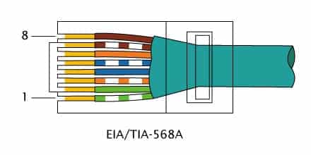
- Pin 1: Green stripe
- Pin 2: Green solid
- Pin 3: Orange stripe
- Pin 4: Blue solid
- Pin 5: Blue stripe
- Pin 6: Orange solid
- Pin 7: Brown stripe
- Pin 8: Brown solid
An illustration of the EIA-568A pinout is shown below.
Cable wire purposes
Why does an Ethernet cable have eight wires in it? Does it matter which color goes where in a connector? The answers to these two questions are surprising.
First of all, the UTP cable that is always used for Ethernet networks doesn’t need to contain eight wires. However, this is the convention. The blue pair and the brown pair don’t do anything.
The wires within the colored jackets are all identical. If you strip the casing of the blue-striped wire, it looks exactly the same as the orange solid wire when that is stripped. The fact that there are two different sets of guidelines for wiring an RJ-45 could lead to chaos. However, it really doesn’t matter which order you put the wires in, just as long as you put the same color in pin 1 in the connectors at either end and the same color in pin 2 and so on.
DTEs and DCEs
The socket that the RJ-45 fits into is soldered onto a network card. Every piece of equipment that can connect to a cabled network has to have a network card, which is also known as a network interface controller, or NIC. There are actually two types of devices that connect to a network: DTEs and DCEs. DTE stands for “data terminal equipment.” This refers to your computer. A DCE is “data circuit -terminating equipment.” This means any network device, such as a modem, a router, or a switch.
The distinction between DTEs and DCEs is important when you want to work out whether to use a straight through cable, or a crossover cable.
Connector pin purposes
The important factor to remember when wiring RJ-45 plugs is the function of each pin. The following list shows the purpose of each connector within the 8P8C plug that fits into the DTE:
- Pin 1: Transmit positive signal
- Pin 2: Transmit negative signal
- Pin 3: Receive positive signal
- Pin 4: Nothing
- Pin 5: Nothing
- Pin 6: Receive negative signal
- Pin 7: Nothing
- Pin 8: Nothing
The connections within the socket on either side have to correspond with each other. There is no point in a DTE transmitting data down pins 1 and 2 if the DCE on the other end also regards those pins as connections it should send data over. So the sockets on a DCE are wired in reverse. Here is the pin purpose as far as a DCE is concerned:
- Pin 1: Receive positive signal
- Pin 2: Receive negative signal
- Pin 3: Transmit positive signal
- Pin 4: Nothing
- Pin 5: Nothing
- Pin 6: Transmit negative signal
- Pin 7: Nothing
- Pin 8: Nothing
So a DTE transmits on pins 1 and 2 and receives on pins 3 and 6. A DCE transmits on pins 3 and 6 and receives on pins 1 and 2.
Straight-through cable
- Usage: Connects different types of devices (e.g., computer to switch or router).
- Wiring Configuration: Both ends of the cable have the same wiring order.
- Common Scenario: Used to connect a computer’s NIC (Network Interface Card) to a switch’s port.
A straight-through cable is often called a wired patch cable or an Ethernet cable. The cable that comes in the box with your router is a straight through cable – it is the most common format for network cables. The straight through cable is configured as described above. It doesn’t matter whether the cable you buy follows EIA-568A or EIA-568B because in both cases, the same color wire connects to the same pin at either end. This is the cable you use to connect a DTE to a DCE. There is no wrong end. The connectors on both ends are exactly the same and the socket on your computer that the cable plugs into is exactly the same (externally) as the plug on your router or modem that takes the cable connector.
Printer cables
Parallel Printer Cable (Centronics or IEEE 1284):
- Usage: Historically used to connect printers to computers, especially in the era before USB became prevalent.
- Physical Appearance: Features a 25-pin DB-25 connector on one end (for the computer) and a 36-pin Centronics connector on the other end (for the printer).
- Speed: Generally slower than USB, suitable for older printers and legacy systems.
USB Printer Cable (USB Type A to Type B):
- Usage: Most modern printers use this type of cable to connect to computers.
- Physical Appearance: One end has a standard USB connector (Type A) which plugs into the computer, while the other end has a square-shaped USB Type B connector for the printer.
- Speed: USB 2.0 offers speeds up to 480 Mbps, while USB 3.0 and later versions can offer even faster data transfer rates.
Printer cables are tricky. If you connect your printer to a switch, then you need a straight through cable. Conventionally, you can’t use a straight through cable to connect your printer to your computer. This is because both your computer and your printer are DTEs. Both will regard pins 1 and 2 as transmission channels and both will listen for incoming data on pins 3 and 6. So if your computer is sending data down pins 1 and 2 and your printer is listening on pins 3 and 6 that printout is never going to happen. In this instance, you need a crossover cable.
Crossover cables
- Usage: Connects similar devices directly (e.g., computer to computer or switch to switch).
- Wiring Configuration: The Tx (transmit) and Rx (receive) pins are crossed between connectors on either end. Typically, the green and orange pairs are swapped.
- Common Scenario: Useful for direct device-to-device network testing or setup without intermediary equipment.
A crossover cable does exactly as its name suggests, it crosses over the wire from pin 1 at one end to pin 3 at the other connector. The wire that is crimped to pin 2 at one end is attached to pin 6 at the other end and the pins 3 and 6 wires go to pins 1 and 2 respectively in the other connector. The crossover cable follows both EIA-568A and EIA-568B. It is A at one end and B at the other. So those conflicting standards did end up being useful.
To pass your CCNA exams, you just need to know that the pin that the striped orange wire connects to on the left of the diagram takes the striped green wire on the right of the diagram. The pin that takes the solid green wire on the left, takes the solid orange wire on the right. You could also write down orange left and green right and you would still get full marks.
Straight through or crossover
If you want a cable to connect your computer and printer together, you need a crossover cable. If you have several computers and one printer, you need to buy a switch. All of the computers will connect to the switch with a straight through cable and your printer would also connect to the switch with a straight through cable.
Remember, two types of devices that connect to networks. When you connect two devices of different types together, you use a straight through cable. When you connect two devices of the same type together, you use a crossover cable. All cables are straight through if you insert a network device between two devices of the same kind. When you need to buy a network cable, define the devices that you want to plug each end of the cable into by the DTE/DCE categories. This list should clarify the configuration of cable that you need.
- DTE to DCE: straight through cable
- DTE to DTE: crossover cable
- DCE to DTE: straight through cable
- DCE to DCE: crossover cable
The cable used for both the straight through and crossover formats is exactly the same. The difference between straight through and crossover cable is that in the crossover configuration the color-covered wires that stick out from the frayed ends of the cable are wired into the plug differently at one end.
There is no DTE end or DCE end in network cables. You can’t plug them in the wrong way. If the same colored wires connect to the same pins in the connectors at both ends, you can plug either end into your computer and the other end into your router. It doesn’t matter. If the wiring sequence is different between the two ends, it doesn’t matter which end you plug into your computer and which goes to your printer.
One more pointer for those sitting the CCNA exams, the wiring diagram for straight through cable in the test shows the EIA-658B pinout at both ends.
MDI and MDI-X
MDI (Medium Dependent Interface):
- Description: Standard interface for NICs (Network Interface Cards).
- Functionality: Traditionally listens for transmissions on pins 3 and 6.
- Modern Implementation: Some modern devices with MDI capabilities can automatically detect on which wires transmissions are arriving, eliminating the strict need for specific pin listening.
MDI-X (Medium Dependent Interface – Crossover):
- Description: A version of MDI that implements an internal crossover, meaning the transmission pins and receiving pins are swapped inside the device.
- Purpose: Traditionally used in hubs and switches to accommodate straight-through cables when connecting to devices like computers.
Auto-MDIX:
- Description: A technology where the device can automatically detect the type of cable (straight-through or crossover) and configures the connection appropriately.
- Advantage: Removes the worry about whether to use a straight-through or crossover cable. The device will adjust itself accordingly.
Away from the CCNA exams, there is one more complication to take into account when you are buying network cables. If your device implements MDI and MDI-X, you don’t need to worry about crossover cables. MDI is the Medium Dependent Interface standard and it operates inside the socket of a NIC. It can detect which wire transmissions arrive on rather than doggedly listening on pins 3 and 6. MDI-X stands for Medium Dependent Interface – Crossover. So, if your computer, printer, switch, router or modem has MDI printed on the box, you only need to buy a straight through cable.
Rollover cable
- Usage: Primarily used to connect a computer to a router’s console port for configuration.
- Wiring Configuration: The order of the wires is reversed from one end to the other. Pin 1 of one end is connected to Pin 8 of the other end, Pin 2 to Pin 7, and so on.
- Physical Appearance: Often has a light blue color to distinguish it from other cables.
These days, you shouldn’t have to worry about rollover cables. They simply reverse the pin order of each wire in a cable. The wire that connects to pin 1 at one end goes to pin 8 at the other end, the wire that goes to pin 2 and the first end goes to pin 7 at the other end. In the middle of the connector pins 4 and 5 are reversed. This format is used for RS-232 connectors that attach to serial ports on computers, printers, or monitors. Serial ports are old news and you shouldn’t need to worry about buying a rollover cable.
Cable casing colors
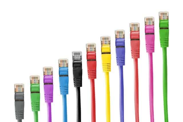
You may see network wired cables that are gray, while others are yellow, some are blue, and then there are white ones. Why? Most cable networking professionals will tell you that the cable jacket color has no meaning; it is just a question of aesthetics. They are partially right. The contents of the cable are exactly the same no matter what the plastic jacket color is. However, cable manufacturers don’t just produce different colored cable jackets for the fun of it.
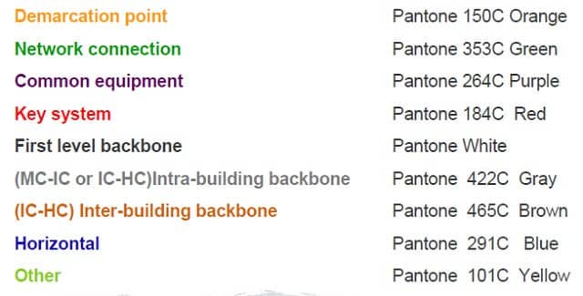
There is an industry standard to which these colors are meaningful. Whether you choose to follow that convention is up to you – most sites don’t pay attention to the standard. The Building Industry Consulting Service International (BICSI) propagates standards for integrating IT services in structures. Among the standards that it promotes is EIA-568, which you have already read about. Another standard is the Administration Standard for the Telecommunications Infrastructure of Commercial Buildings, also known as ANSI/TIA/EIA-606-B (PDF). This is where those cable colors originate. The meanings of cable colors are as follows:
- Orange: Demarcation point
- Green: Network connection
- Purple: Common equipment
- Red: Key system
- White: First level backbone
- Gray: Intra-building backbone (MC-IC or IC-HC)
- Brown: Inter-building backbone (IC-HC)
- Blue: Horizontal
- Yellow: Other
Here is an image of the color coding section of the EIA-606-B standards document where these colors are defined.
Learn about network cables
Network creation, maintenance, and administration is a very satisfying career path. It is a very technical field and you will encounter a lot of academic and theoretical information on the topic. However, it is also a very important real-world factor that keeps the wheels of commerce turning. As you become more proficient in cable networking theory and practice you will contribute more to the economy and help the world thrive. Your starting point is knowing how to crimp a connector onto the end of a network cable.
Now that you know about the layout of networking cables and how to connect them to devices, you are on your way to becoming a network engineer or a network administrator! We hope you have enjoyed our cabling guide.
Networking Cables FAQs
How are crossover cable, rollover cable, and straight cable made?
A length of UTP cable becomes a crossover cable, a rollover cable, or a straight-through cable when someone crimps a connector to each end of it. The order in which the inner wires go into the connectors determines whether it is a crossover, rollover, or straight-through cable.
Why did a straight through cable work when I connected a router to another router?
Although convention states that a connection between two routers (DCE to DCE) requires a crossover cable, a straight-through cable will work if either or both of the devices implements the Medium Dependent Interface (MDI) standard. This detects which wires to listen on for incoming data and thus determines which wires should be used for transmission, so the wiring within the connector doesn’t matter.
Which tools are required for making straight through cable?
The tools needed to transform a network cable and two RJ-45 connectors into a straight-through cable are:
- A crimping tool with the capacity for eight wires. This will also include a wide cutter.
- A stripper tool to peel off the outer jacket of the cable and the individual jackets around the inner wires. You could use a pair of scissors for this.
- A cable tester to check the connection once it has been fitted.
Images:
EIA-568A from Wikimedia Commons. Public Domain.
EIA-568B from Wikimedia Commons. Public Domain.
Network cable colors from PXHere. Public Domain.



Pins 4-5 and 7-8 are often used for Power Over Ethernet now, so saying they are ‘nothing’ is no longer accurate. In any case, I have also run across equipment that would share a network and a ‘standard’ telephone ( or POTS ) connection, with wires 4 and 5 used for that. [ That was back in the ‘good old days’. You know, when all of our packets were delivered by passenger pigeon! ]
Thank you for the lesson. Very well explained. Nice review of what I’ve learned a long time ago. Knowledge enhancing.
I find this very useful as somethings I knew earlier but the blog is just amazing for beginners as some things are here too for Engineers
Thank you very much – this is the best article on this topic I’ve found on the internet. I really appreciate it.
Lets say im running a cat6 cable from a switch to a computer. i want to put a keystone plug in the wall between these connections. should the plug be the wiring standard of the switch or the computer?
it’s very helpfully
They have been of help