In computer networking, protocols operate within a structured framework known as the network protocol stack. This conceptual framework consists of multiple layers, each with specific roles and responsibilities in facilitating communication between devices. Two primary models define these layers: the widely adopted TCP/IP model and the Open Systems Interconnection (OSI) model.
The TCP/IP model, fundamental to the internet, focuses on four layers:
- Network Access
- Internet
- Transport
- Application
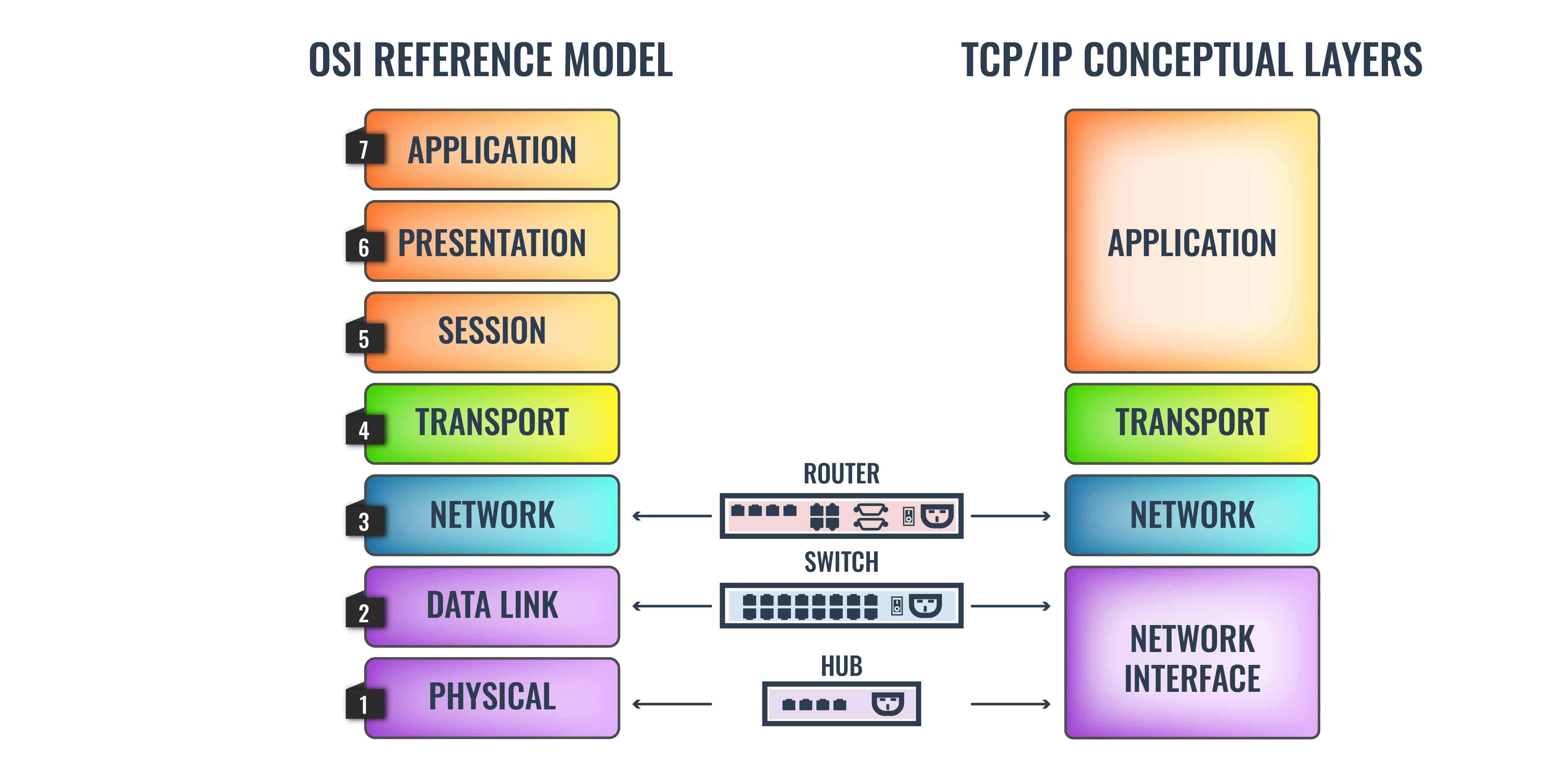
Conversely, the OSI model offers a more detailed seven-layer structure, encompassing:
- Physical
- Data Link
- Network
- Transport
- Session
- Presentation
- Application
Understanding these models is crucial for anyone working with network technologies, as they form the basis for designing, implementing, and troubleshooting network systems. The OSI model, despite being less commonly implemented in its entirety, serves as a universal reference that helps professionals understand where protocols fit within the broader networking landscape.
At the second layer of these models lies the Data Link layer, which plays a pivotal role in node-to-node communication. This layer is responsible for establishing, maintaining, and terminating connections between devices on the same network. Layer 2 protocols, such as Ethernet, VLANs, and Spanning Tree Protocol (STP), ensure reliable data transmission, prevent loops, and manage traffic within local area networks (LANs).
This guide provides an in-depth exploration of Layer 2 protocols, their functions, and their importance in modern networking. Whether you are setting up a simple LAN or managing a complex network infrastructure, understanding Layer 2 is essential for optimizing performance and ensuring seamless communication.
TCP/IP
TCP/IP was originally one protocol – the Transmission Control Program (TCP). In the 1970s, when TCP/IP was first developed, there were several competing protocols in circulation but most of them were proprietary, which meant that networks developed with them were intentionally unable to communicate with each other. The open publication of TCP made it popular in academic circles because it was easier to teach. Thus, more technologists graduated with knowledge of the system.
The flexibility and universality of TCP were enhanced when its different functions were split out into layers in 1974 to create TCP/IP – Transmission Control Protocol/Internet Protocol. TCP/IP was now becoming an extensive body of documents and the layering concept simplified the perception of how collections of protocols can work together through “layers of abstraction”.
The layering idea of TCP/IP was great but it wasn’t very well implemented. Essentially, the system started with only two layers: Network Layer, which dealt with infrastructure issues, and Transport Layer, which contained session-related protocols.
It was clear that the Network Layer dealt with two types of networks: the LAN and the Internet. Eventually, the Network Layer was split out so that local network systems were defined as the lowest layer, called the Network Interface Layer, and interconnection systems remained in the Network Layer, which is between the Network Interface Layer and the Transport Layer.
OSI
The Open System Interconnection model was defined by the International Standards Organization (ISO) and was first released in 1980. This protocol stack has finer granularity and includes seven layers.
The OSI schematic is also known as the 7-Layer Model and its strata are numbered from 1 at the bottom to 7 at the top. Layer 1 is the Physical Layer and it includes definitions of hardware, such as network cable standards. Layer 2 is the Data Link Layer. It contains protocols that manage the movement of data around a local network, with issues such as device addressing and data frame layout. Internet issues, such as IP addresses are at Layer 3, which is called the Network Layer.
The term “Layer 2” derives from the OSI model and refers to the Data Link Layer.
TCP/IP vs OSI
The OSI reference model is a much better plan than TCP/IP. However, by the time it came out, TCP/IP was already established in commercial implementations and new graduates who were educated in the superiority of OSI had to toe the line with senior network managers with their TCP/IP viewpoint to get work.
To quell the argument between the two tribes, a silent settlement was agreed upon. While the youngsters agreed to shut up about OSI, their elders and betters quietly added OSI features to TCP/IP. You will notice that representations of TCP/IP, there is now a large Application Layer block at the top of it – that first appeared towards the end of the 1990s and is not included in the official definition of the stack.
Another quiet change in the typical TCP/IP diagram is that the stack has now been jacked up with a (Hardware) ghost layer beneath it. This makes the Network Interface Layer, Layer 2 in TCP/IP as well as in OSI.
Layer 2 devices
Layer 2 is implemented on networks by the switch. This device is a packet switching system and, importantly, it has an onboard computer. The back of the switch has an array of slots into which network cables are connected.
When data travels across a network, it passes over a cable from a device to a switch, this stretch is called a link. No message ever actually goes from source to destination over one piece of cable, there will always be a switch in the path.
There are no physical connections within the switch. Data arriving in from one cable has, effectively, reached its destination. The data is read into the switch’s memory. The switch will then write out that data to a connector for another cable that leads to another device.

A network might have many switches, in which case, there will be one cable running from one switch to another switch. Thus, the switches are chained together and each switch will have cables leading to many endpoints.
The choice of output cable made by the switch when it has incoming data to forward is dictated by the information that is tacked onto the front of the data. The format for data transmission is a datagram, which is called a “frame” in Layer 2 parlance. The address on the front of a frame is a MAC address. This MAC address is the serial number of a device’s network card.
MAC address doesn’t relate to Apple Macintosh computers. MAC stands for “Media Access Control”, which you will read more about later. Every Mac has a MAC address and so does every Windows PC. Every device that can connect to a network has a MAC address.
Every MAC address in the world is unique and it is hard-coded onto a network card. The switch uses an auto-detect process when a cable is plugged into it. The switch queries the device at the other end of the cable and acquires its MAC address. The switch then associates that MAC address with the number of the socket that the device’s cable is plugged into.
The sockets in a switch are called “ports”. This is a confusing term in networking because it is also used to denote the numbers assigned to applications/protocols. To clear up the confusion, these sockets are often called “switch ports”. Some network monitoring tools offer a service that is called a “switch port mapper”.
Layer 2 sub-layers
There is one more issue to tackle before we look at Layer 2 protocols: the Data Link Layer has two sub-layers. Thanks to the (Hardware) Layer that was slid under the TCP/IP stack, local network functions are now termed Layer 2 in both models. However, the TCP/IP Network Interface Layer doesn’t have any sub-layers. Thus, we are now back to referring to the OSI model.
The two sub-layers of the Data Link Layer are:
- Logical Link Control (LLC)
- Media Access Control (MAC)
When stratified in a diagram, the Logical Link Control sublayer is placed above the Media Access Control sublayer.
Logical Link Control
The LLC sublayer ensures that a frame reaches its destination. This group of tasks involves issues such as confirmation of receipt and the view of a frame traveling through switches. Subjects covered by LLC protocols include flow control and error/loss resolution. This system mimics the two main Transport Layer systems – Transmission Control Protocol (TCP) and the User Datagram Protocol (UDP) because it offers options to use connection-oriented and connectionless services.
Media Access Control
The MAC sublayer is concerned with the way access to the cable is implemented and also the way that transmitters and receivers coordinate the bit interpretations and identify the start and end of each frame. The Media Access Control sublayer is where the name for the MAC address comes from.
Layer 2 protocols
The purpose of Layer 2 is to perform routing on the local network. It feeds into the Layer 3 functions of routers, which send data out of a network and across other networks. So, when your computer contacts the server for a Web page, the request crosses the local network to the router, across the internet, and then over the remote network to the server. That journey can be broken down into Layer 2 -> Layer 3 -> Layer 2.
When trying to work out whether a protocol is Layer 2 or Layer 3, the simple test is whether the protocol is needed to get data over to another network or if it operates within a local network.
Working out which are LLC and which are MAC protocols is a bit harder than allocating a protocol to Layer 2. The two sublayers are packaged together because their responsibilities don’t always stratify neatly and some protocols cover the conceptual remit of both.
An example of the confusing scatter of protocols between these two sublayers lies with the Address Resolution Protocol (ARP). This maps between IP addresses (Layer 3) and MAC addresses (Layer 2), so thinking about the stratified layers of service, you would expect this function would lie in the upper sublayer of the Data Link Layer because it is closest to the next layer up, the Network Layer, where IP resides. However, it isn’t – ARP is a MAC function.
LLC protocols
LLC is primarily concerned with flow control and error management, so the protocols in this sublayer include systems, such as:
- Link Access Procedure, Balanced (LAPD) This is part of the X.25 suite of protocols. LAPB sets out processes for assuring transmission between suits and endpoints in either direction.
- High-Level Data Link Control (HDLC) This is the precursor of LAPD and it has also been implemented as a protocol in telephone networks. The purpose of this system is to define three modes of control on communications – the only one of these that is active today is Asynchronous Balanced Mode (ASM), which defines how data should move from one endpoint to another. Some HDLC derivatives also include MAC functions, giving this protocol a spread across the two sublayers.
- Point-to-Point (PPP) Confusingly, this protocol is designed for use between routers. It supplies the Layer 2 functions needed when two servers communicate directly through routers and without local networks to traverse. Variations Point-to-Point over Ethernet (PPPoE) and Point-to-Point over ATM (PPPoA) are used by ISPs to establish connections with subscribers and authenticate their access requests.
- IEEE 802.2 This is the definition of LLC from the Institute of Electrical and Electronics Engineers and it allows LLC functions to be integrated into Ethernet (IEEE 802.3) and Wi-Fi (IEEE 802.11) protocol groups.
- Layer 2 Tunneling Protocol (L2TP) This is a security system that is used for virtual private networks (VPNs). The system establishes a session and does not itself provide any encryption, which is furnished by related protocols. This system is used in conjunction with IPSec, which does provide encryption when connections include routes across the internet.
MAC protocols
MAC prepares the data frame and this task has to be detected according to the transmission system in use – some systems have a fixed datagram length. This service is also involved in checking for clearance before applying the frame to the wire of the network.
As well as the responsibility for addressing and stream identification, such as VLAN tagging, the MAC protocols include:
- Carrier-sense Multiple Access with Collision Detection (CSMA/CD) This is the media access control method used for wired networks, as specified in the IEEE 802.3 protocols. It defers action until the line is clear. This system keeps checking for other transmissions while its output is in transit.
- Carrier-sense Multiple Access with Collision Avoidance (CSMA/CA) This is the media access control method used in the Wi-Fi standards, which are defined by IEEE 802.11. This system checks for an idle channel before transmitting but does not continue to check for clearance during transmission.
- Spanning Tree Protocol (STP) This is a routing algorithm that accounts for the possibility of multiple network paths resulting in a feedback loop that could recirculate the same frames around the network.
- Shortest Path Bridging (SPB) A routing system that decides on a path through a network that has multiple routes through to a destination.