Setting up a VLAN (Virtual Local Area Network) is a fundamental network configuration task that allows you to logically segment a network without changing its physical layout. VLANs are used to improve network performance, enhance security, and simplify management by dividing a single physical network into multiple logical networks.
By grouping devices on the same VLAN, even if they’re physically dispersed, you control and isolate network traffic, reduce broadcast traffic, and manage different user groups more efficiently.
VLAN setup is beneficial in various environments, from small offices to large enterprise networks, as it allows better control over network resources, minimizes security risks, and facilitates efficient troubleshooting. Whether segmenting traffic by department, user type, or security level, VLANs are essential for creating a flexible, scalable, and secure network infrastructure.
The process of creating a VLAN typically involves configuring network switches to assign specific ports or devices to a VLAN, assigning each VLAN a unique ID, and setting up IP address ranges for each VLAN. Devices within a VLAN can communicate with each other directly, but traffic between different VLANs requires inter-VLAN routing, typically through a router or Layer 3 switch.
A Layer 3 switch combines switching and routing capabilities, enabling high-speed data forwarding within networks and facilitating inter-VLAN routing, enhancing network performance and management. So, if you’ve got the right equipment, let’s get started with setting it up.
Note: while we have tried to make the whole exercise of setting up a VLAN as simple as possible, it is assumed that you, the reader, have a basic grasp of network configuration. We also assume that you have a working knowledge of the concepts, and purposes, of IP addresses, gateways, switches, and routers. In addition, you also need to know about navigating the interface and sub-interface configuration procedures on computers and networking devices.
Step-by-step – How to set up a VLAN
The best way to learn how to set up a VLAN – apart from going to networking school – is to actually do it in a practical exercise. And since we don’t all have routers and switches lying about, it would make sense to create our VLAN in a simulated environment.
Using Cisco Packet Tracer for VLAN Configuration
In this example, we will be using Cisco Packet Tracer to demonstrate how to set up our VLAN. It is one of the easiest, and most realistic, tools to use and allows for both GUI and CLI interfaces. This way you can see the commands that are being executed in real-time even though you are simply clicking and drag-and-dropping as you go about your configuration.
Downloading and Accessing the Tool
The tool can be downloaded, set up, and verified (by opening a learning account at Cisco Networking Academy). Don’t worry; you can simply sign up for the FREE Cisco Packet Tracer Course in order to gain full access to the design tool.
Also, and apart from the ease-of-use, with Cisco being the market leader, we think this is the appropriate choice to demonstrate how to set up a VLAN.
Alternative Tools for VLAN Configuration
Of course, you can use any other similar tool – because the concept remains the same. A quick online search will show you there are applications – desktop as well browser-based – for every brand of network interface devices out there. Find and work with the one you are most comfortable with.
Understanding the Router-on-a-Stick Configuration
Architecture Overview
While there are many ways of setting up a VLAN or inter-VLAN, the architecture we will be creating will be making use of what is known as a Cisco Router on a Stick configuration.
Physical and Logical Connections
In this network configuration, our router will have a single physical or logical connection to our network. This router will help bridge the two VLANs – that cannot communicate with one another – by connecting to our switch via a single cable.
Data Packet Journey
Here’s how it works: data packets that are sent out from a computer in the Accounting VLAN – and intended for a computer in the Logistics VLAN – will travel to the switch. The switch, upon recognizing the packets need to cross over to another VLAN, will forward the traffic to the router.
Understanding Sub-Interfaces
The router, meanwhile, will have one physical interface (a network cable, in our example) that has been split into two logical sub-interfaces. The sub-interfaces will each be authorized to access one VLAN.
Packet Forwarding Mechanism
When the data packets arrive at the router, they will be forwarded to the correct VLAN via the authorized sub-interface and then arrive at their intended destination.
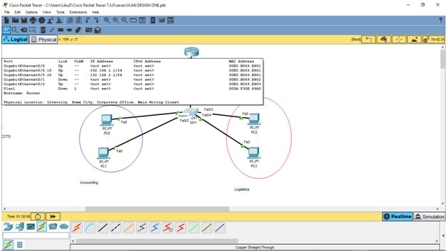
Our Router on a Stick VLAN setup, with inter-VLAN capabilities, will look like this:

Planning your tasks
The whole task of creating our network architecture will be divided into four main categories where you will:
- Connect all devices to form the correct architecture
- Configure interfaces so all the devices can “talk” to one another
- Create VLANs and assign computers to their respective VLANs
- Confirm correct configuration by demonstrating the computers cannot communicate beyond their VLAN
So, without further ado, let’s start creating our VLAN. Remember, it will initially have a switch and four computers connected to it. You can bring the router into the design later if you choose to do so.
Connect all devices
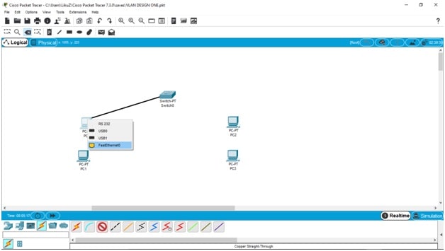
Drag and drop a switch, a router, and four computers into the main design board. For our demo, we will be using a 2960 switch and a 2911 router. The switch will connect to four computers (PC0, PC1, PC2, and PC3) using copper straight-through wire connections (you will see the description of the hardware and connection types at the very bottom of the Tracer window).
Next, connect the switch to each computer using the FastEthernet ports.
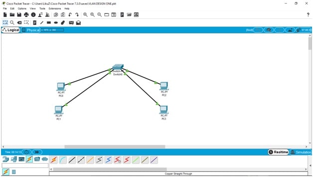
Once all devices are connected you should have all-green traffic flowing between the devices. As the tool tries to emulate devices booting and connecting in the real world, it might take a minute or two. So don’t worry if the data flow indicators remain orange for a few seconds. If your connections and configurations are correct, it will all soon change to green.
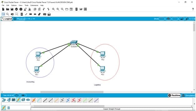
To make things easier to grasp, let’s mark the two computers on the left as belonging to the Accounting department (blue) and the other two as belonging to the Logistics departments (red).
Configure interfaces
Now, let’s start assigning IP addresses so our computers can start communicating with one another. The IP assignments will look like this:
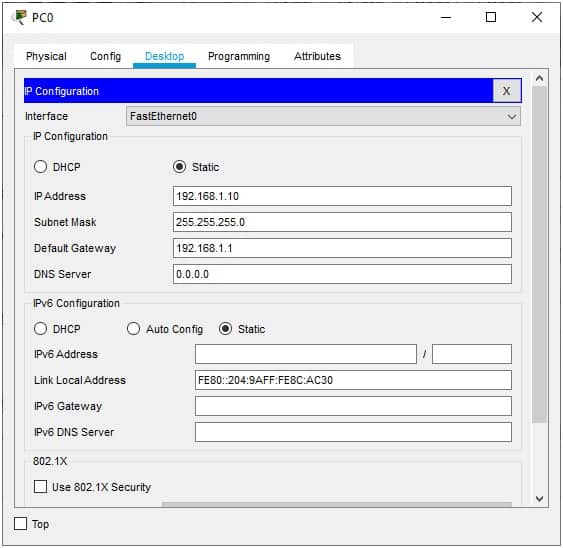
- ACCT PC0 = 192.168.1.10/255.255.255.0
- ACCT PC1 = 192.168.1.20/255.255.255.0
- LOGS PC2 = 192.168.2.10/255.255.255.0
- LOGS PC3 = 192.168.2.20/255.255.255.0
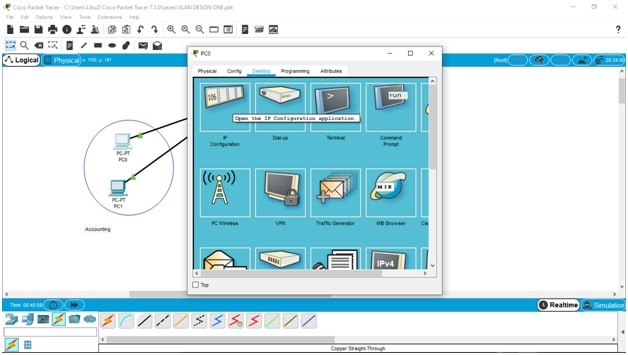
The default gateway for the computers is 192.168.1.1 for the first two in Accounting, and 192.168.2.1 for the last two computers in Logistics. You can access the configuration by going to the Desktop menu and then clicking on the IP Configuration window.
Once you’re there, start filling in the configurations for all the computers:
When you are done, we can now move on to the switch. First, though, we need to remember that there will be two types of ports on our switch:
- Access Ports: these are the ports that will be used to allow everyday devices like computers and servers to connect to it; in our example, these are the FastEthernet 0/1, FastEthernet 1/1, FastEthernet 2/1, and FastEthernet 3/1 – one for each computer.
- Trunk Ports: these are the ports that allow a switch to communicate with another switch – or in our example a VLAN-to-VLAN communication on the same switch (via the router) – to expand the network; we will use the GigaEthernet0/0 ports on both the connectivity devices.
With that in mind, let’s move on to the fun part – configuring the switch to run our VLANs.
Create VLANs and assign computers
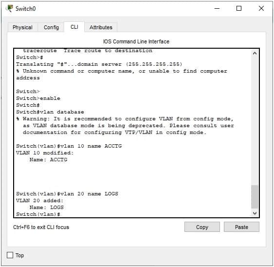
So, let’s create the VLANs first – they will be named ACCT (VLAN 10) and LOGS (VLAN 20).
Go to the switch’s CLI to type in the commands:
Switch#config terminal

Switch(config)#vlan 10

Switch(config-vlan)#name ACCT

Switch(config-vlan)#vlan 20

Switch(config-vlan)#name LOGS
The commands in your CLI should look like this:
Or, if you’re not up to it, you can simply use the GUI to create the VLANs (and still see the commands run as they are being executed below). Go to the Config-VLAN Database menu and ADD the VLANs by entering their numbers (10,20) and names (ACCT, LOGS).

Next, we need to assign each port, which the switch uses to connect the computers, to their respective VLANs.
You can simply choose the interface and then check the box of the corresponding VLAN from the configuration menu on the right:
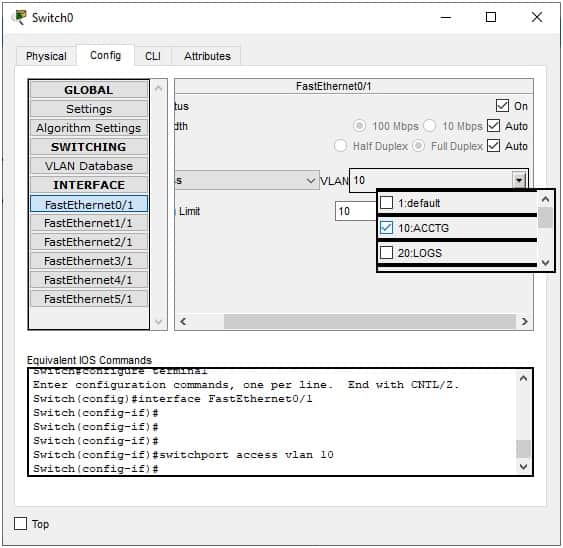
As you can see from the image above, you can alternatively go into the CLI interface of each port and use the command: switchport access vlan 10 to perform the same task.
Don’t worry; there is a shorter way of doing this in case there are a large number of ports to assign. For example, if you had 14 ports, the command would be:
Switch(config-if)#int range fa0/1-14

Switch(config-if-range)#switchport mode access
The second command makes sure that the switch understands the ports are to be ACCESS ports and not TRUNK ports.
Confirm correct configuration
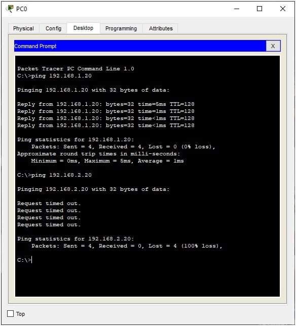
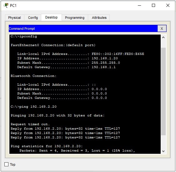
And that’s it; we have created two VLANs on the same switch. To test it, and confirm our configuration is correct, we can try pinging P1 and P3 from P0. The first ping should be fine while the second one should time out and lose all the packets:
How to set up an inter-VLAN
Rationale Behind Inter-VLAN
Now, although we have divided the computers into two VLANs – as was required – it makes more sense that the two departments (Accounting and Logistics) would need to communicate with one another. This would be the norm in any real-life business environment. After all, logistics couldn’t be purchased or supplied without financial backing, right?
Objective of Inter-VLAN Setup
So, we need to make sure that ACCT and LOGS are able to communicate – even if they are on separate VLANs. This means we need to create an inter-VLAN communication.
Initial Setup Requirements
Here’s how to go about it!
We will need the help of our router; it will act as a bridge between the two VLANS – so, go ahead and add a router to your design if you haven’t already done so.
Router and Switch Configuration
Jumping into the configuration, we must understand that we will use one port on the router for both VLANs’ communication by “splitting” it into two ports. Meanwhile, the switch will only use one TRUNK port to send and receive all communications to, and from, the router.
Sub-Interface Creation and Configuration
So, going back to our router, we will split the GigabitEthernet0/0 interface into GigabitEthernet0/0.10 (for VLAN10) and GigabitEthernet0/0.20 (for VLAN20). We will then use the IEEE 802.1Q standard protocol for interconnecting switches, routers, and for defining VLAN topologies.
Assigning the Sub-Interfaces
Once done, these “sub-interfaces” – as they called – are then assigned to each VLAN that we want to connect or bridge.
Setting IP Addresses for Sub-Interfaces
Finally, remember the gateways – 192.168.1.1 and 192.168.2.1 – we added to the computers’ configurations earlier? Well, these will be the new IP addresses of the split ports or sub-interfaces on the router.
The CLI commands to create the sub-interfaces under the GigabitEthernet0/0 interface would be:
Router (config)#interface GigabitEthernet0/0.10

Router (config-subif)#encapsulation dot1q 10

Router (config-subif)#ip address 192.168.1.1 255.255.255.0
Repeating it all for the second sub-interface and VLAN we get
Router (config)#interface GigabitEthernet0/0.20

Router (config-subif)#encapsulation dot1q 20

Router (config-subif)#ip address 192.168.2.1 255.255.255.0
Once you close the CLI, you can confirm your configuration is correct by simply moving the mouse over the router to see your work, which should look something like this:
Now, we know that we can only connect our sub-interfaces (on the router) to our switch via its trunk port – and so, we will need to create it now.
All you need to do is go in the switch’s GigabitEthernet0/0 configuration and run: switchport mode trunk.
And there you have it; you have just created two VLANs that contain two computers each and which can still communicate with one another. You can prove this by pinging the first Logistics computer (PC2) with IP address 192.168.2.10 from the first Accounting computer (PC0) with the IP address 192.168.1.10:
Great Success!
Why set up a VLAN or inter-VLAN
At this point, some of you may be wondering why we would need to go through this exercise and bother with VLANs or inter-VLANs at all. Well, there are many reasons, some of which are:
- Security Breaking up a network into components ensures that only authorized users and devices can access a sub-network. You wouldn’t want your accountants to interfere with the work of your logistics department or vice versa.
- Safety In case there is a virus outbreak, only one subnet would be affected as the devices on one subnet wouldn’t be able to communicate – and thus transfer – the virus to another one. This way, clean-up procedures would be focused on that one subnet which also makes it easier to identify the culprit machine a lot faster.
- Ensures privacy by isolation If someone wanted to find out about your network’s architecture (with the intent of attacking it), they would use a packet sniffer to map out your layout. With isolated sub-networks, the culprits would only be able to get a partial picture of your network thus denying them critical information about your vulnerabilities, for example.
- Eases network traffic Isolated sub-networks can keep traffic usage down by keeping resource-intensive processes limited to their own scope and not overwhelming the whole network. This means, just because IT is pushing critical updates to the accounting machines, doesn’t mean the logistics department has to face a network slowdown too.
- Traffic prioritization With businesses that have various types of data traffic the sensitive or resource-hogging packets (VoIP, media, and large data transfers, for example) can be assigned to a VLAN with larger broadband while those that only need the network to send out emails can be assigned to a VLAN with lesser bandwidth.
- Scalability When a business needs to scale-up the resources available to its computers it can reassign them to new VLANs. Their administrators simply create a new VLAN and then move the computers into them with ease.
As we can see, VLANs help protect a network while also improving the performance of the data packets that travel around it.
Static VLAN vs Dynamic VLAN
We thought it would be worth mentioning that there are two types of VLANs that available for implementation:
Static VLAN
This VLAN design depends on hardware to create the sub-networks. The computers are assigned to a specific port on a switch and plugged right in. If they need to move to another VLAN, the computers are simply unplugged from the old switch and plugged back into the new one.
The problem with this is that anyone can move from one VLAN to another one by simply switching the ports they are connected to. This means administrators would require physical security methods or devices put in place to prevent such unauthorized accesses.
Dynamic VLAN
This is the VLAN we have just created in the exercise we did earlier. In this VLAN architecture, we have software VLANs where the administrators simply use logic to assign specific IP or MAC addresses to their respective VLANs.
This means devices can be moved to any part of the business, and as soon as they connect to the network, they return to their pre-assigned VLANs. There is no need for additional configurations.
If there is one drawback with this scenario, it can only be that the business would need to invest in an intelligent switch – a VLAN Management Policy Switch (VMPS) – which can be on the expensive side when compared to the traditional switch used in static VLANs.
It can also be safely assumed here that businesses with a few computers and a smaller IT budget can choose to implement a static VLAN while those with a large number of devices and a need for more efficiency and security would be wise to invest in a dynamic VLAN.
Conclusion
We hope you have found all the information you needed to learn about how to set up a VLAN. We also hope that the exercise was easy to follow and that you can now go on to build upon the knowledge you have gained. Because, even as you continue to scale upwards, these basic steps remain the same – you simply continue to add hardware and configurations to the basics.
VLAN FAQs
What is a VLAN?
A VLAN is a method that makes networks more efficient by reducing the scope of broadcast transmissions to just a section of the network. A broadcast goes to every part of the network, which can create a lot of traffic all over the system, including to areas that will never need to receive that broadcast or respond to it. Effectively, a VLAN divides up a network into sections.
How is a VLAN different from a LAN?
LAN stands for Local Area Network, which is the common name for a typical network inside an office. The virtual LAN (VLAN) creates sections of that LAN, which seem to be separate systems, even though they are actually all connected together. The segmentation of the LAN into VLANs happens at the Data Link Layer (Layer 2), so it is implemented on switches and bridges.
Routers are at the Network Layer (Layer 3). They operate for the entire network but use software techniques to distinguish between VLAN sections. The router can bridge between these sections with inter-VLAN routing.
What are the types of VLAN?
There are five types of VLAN:
- Default VLAN: Switches have settings that can implement VLANs but these are all initially set to VLAN1. As all switches have the same VLAN, there is only one VLAN operating, which effectively means that the technology is disabled.
- Data VLAN: Also known as a user VLAN, this strategy creates two groups: one for users and one for devices. This ill only carry data.
- Voice VLAN: Meant for the office telephone network and implemented with VoIP, this VLAN carries voice traffic. This traffic gets priority over data traffic to ensure a high quality of service.
- Management VLAN: Accesses the management functions of a switch for tasks such as logging, and extracting activity and status data for system monitoring. When other VLANs are set up, the management VLAN should be left as VLAN1.
- Native VLAN: Used for trunk ports that handle traffic from all VLANs, creating a common transmission channel that traffic can be split out of for individual VLANs.
Thank you. The tutorial was clear and easy to understand. It helped me learn more about VLANs and how they are implemented.
Really nice example. the diagrams are simple yet clear.
Very helpful Thanks
Excellent guide.
Just a small point, remember to turn ON your router port for this to work.
Great article with simple explanation! Cheers
Nice article. Easy to follow and understand.