The Maximum Transmission Unit (MTU) is a critical parameter in networking that defines the largest size of a packet that can be sent over a network interface without needing fragmentation. The MTU value is significant because it directly impacts the efficiency and performance of data transmission over internet connections. If the MTU is too large, packets may need to be fragmented to fit into the smaller MTUs of intermediary network devices, leading to increased overhead and potential delays. Conversely, if the MTU is too small, a higher number of packets are needed to transmit the same amount of data, which can also reduce efficiency.
The standard MTU size for Ethernet is 1500 bytes, but this can vary depending on the network type and configuration. Problems with MTU often arise in scenarios involving different networks with varying MTU sizes, such as when connecting to VPNs, tunnels, or Internet Service Providers (ISPs) that use different standards. Mismatched MTU settings can lead to packet loss, latency, and decreased throughput, which can significantly affect the performance and reliability of internet connections.
Understanding and configuring the correct MTU size is essential for optimizing network performance. Network administrators must ensure that the MTU settings are appropriately aligned across all devices and segments of the network to avoid potential fragmentation issues and to ensure smooth and efficient data transmission.
MTU in a nutshell
MTU is a measurement representing the maximum data packet that a network path, device, or interface will accept. Think of it as being like a height limit for vehicles passing through a particular freeway or tunnel. Vehicles that exceed the height limit cannot fit through, just as packets that exceed the MTU of a network cannot pass through that network. IPv4 and IPv6 require every link to support a specified MTU. These are called the IPv4 and IPv6 minimum link MTU. MTU parameters usually appear in association with a network device interface such as NIC and serial port. Links such as point-to-point networks usually decide MTU at connect time; while network protocols such as Ethernet have a fixed MTU size.
The Ethernet MTU is fixed at 1500 bytes. This means that the largest IP packet or payload an Ethernet frame can contain is 1500 bytes. Network communication protocols usually add overhead (header and frame check sequence) to the payload to be transported. Think of the header as a shipping label attached to a package, and the payload as the package’s actual contents. The header contains information about the packet’s source and destination addresses. The Ethernet frame structure is defined in the IEEE 802.3 standard. Table 1.0 below is a graphical representation of an Ethernet frame structure, including a description of each field in the frame:
| Preamble 7 Bytes | SFD 1 Byte | Destination MAC 6 Bytes | Source MAC 6 Bytes | Type 2 Bytes | Data and Pad 46-1500 Bytes | FCS 4 bytes |
|---|
Table 1.0 | Ethernet frame structure
- Preamble-–informs the receiving system that a frame is starting and enables synchronization.
- SFD (Start Frame Delimiter)–signifies that the destination MAC address field begins with the next byte.
- Destination MAC–identifies the receiving system.
- Source MAC–identifies the sending system.
- Type–defines the type of protocol inside the frame, for example, IPv4 or IPv6.
- Data and Pad–contains the payload data. Padding data is added to meet the minimum length requirement for this field (46 bytes).
- FCS (Frame Check Sequence)–contains a 32-bit Cyclic Redundancy Check (CRC) which allows detection of corrupted data.
So the MTU basically defines how big the payload area can be, including the TCP/IP headers. This value is configurable, which means that you can change it if you want. But it’ll usually fall back to its default size if you don’t tamper with it.
So, which is better you may ask, bigger payload or smaller payload? Well generally speaking larger packets can be a lot more efficient than using smaller packets. With larger packets you know you’re basically transmitting more data but you’re incurring the same overhead cost-–the same Ethernet headers and the FCS sequence as you would with a smaller packet.
However, one major huddle you’ll have to wrestle with is the fact that data packets that exceed MTU will not be allowed to pass through, and you’ll need to make some adjustments to make it work. To get around this issue, IPv4 introduced a mechanism that allows packets to be broken up into smaller chunks so that they can pass through. This mechanism is called fragmentation.
The problem with fragmentation
As novel as the idea of fragmentation may sound, it is not without challenges. Fragmentation adds some degree of insecurity, latency, and inefficiency to network communications. As at the time of writing, IP fragmentation is considered fragile and often laden with security vulnerabilities that can be used to exploit fragmentation. Malicious actors can use attacks such as overlapping fragment attacks, resource exhaustion attacks, teardrop attacks, ping of death, and other denials of service related attacks, to exploit those vulnerabilities.
All fragments of a packet must arrive for the packet to be considered received. Fragmented packets are reassembled once they reach their destination. If a receiving host receives a fragmented packet, it has to reassemble the packet, and all of these add to the latency. When the number of packets that must be fragmented or the number of fragments is great, it can result in unnecessary overhead. And if the network drops any fragment, the entire packet is lost. IP fragmentation can cause excessive retransmissions when fragments encounter packet loss and protocols such as TCP must retransmit all of the fragments in order to recover from the loss of a single fragment.
In certain cases, packets cannot be fragmented, and therefore they will not be delivered if they exceed the MTU of any router or device along the network path. For example, routers that implement IPv6 protocol will drop any IPv6 packets that exceed the MTU, because they cannot be fragmented in IPv6. Secondly, in IPv4 networks, when the “Don’t Fragment” flag is set in a packet’s IP header, the attached packet cannot be fragmented. If the packet exceeds the MTU, the router drops the packet instead of fragmenting it, and immediately sends back a “packet too big” ICMP message (status update) to the source node.
In order to overcome those challenges, you have to figure out the optimal size of IP packets to send over the network. Those packets must be adjusted manually or automatically so as to not exceed MTU. There are two possible ways to achieve this:
- The manual approach is for the sending device to send the optimal packet size or MTU required by the path or receiving device.
- The automatic approach is a technique called Path MTU Discovery, which helps to automatically discover the path MTU between two hosts so that IP fragmentation can be avoided.
Path MTU Discovery and its limitations
Path MTU Discovery (PMTUD) just as the name implies is the process of discovering the MTU on the network path between two nodes, usually with the goal of avoiding IP fragmentation. When PMTUD is in place, a computer trying to send packets to a router would have to identify the router’s MTU requirements and adjust the packet size accordingly to avoid fragmentation. PMTUD works slightly differently for IPv4 and IPv6-based networks.
IPv4 Path MTU Discovery works by setting the “Don’t Fragment (DF)” flag bit in the IP headers of outgoing packets. Then, any device along the path whose MTU is smaller than the packet will drop it, and send back an ICMP “Packet needs to be fragmented” message. This allows the source host to reduce its Path MTU appropriately. The process is repeated until the MTU is small enough to traverse the entire path without fragmentation.
IPv6 does not allow fragmentation, and so the “Don’t Fragment” option does not even exist. Therefore routers that implement IPv6 will not fragment IPv6 packets, so if packets exceed the MTU, the routers drop the packets and send back corresponding ICMP messages without checking for a “Don’t Fragment” flag. This allows the source host to reduce its Path MTU appropriately. The process is repeated until the MTU is small enough to traverse the entire path without fragmentation
In ideal situations, PMTUD operates as described above. However, in some cases, PMTUD fails. According to the Internet Engineering Task Force (IETF), the failure can be attributed to factors such as:
- Blocked ICMP messages: PMTUD relies on the network’s ability to deliver ICMP messages to the source node. However, many network security devices block ICMP messages for perceived security benefits. If the network cannot deliver ICMP messages to the source node, PMTUD fails.
- Malicious attacks: PMTUD is susceptible to attack because ICMP messages are easily forged and not authenticated by the receiver. Such attacks can cause PMTUD to produce unnecessarily conservative PMTU estimates.
A common workaround implemented in some routers is for the network devices to agree and communicate the Maximum Segment Size (the largest data payload that a device accepts from a network connection) of the packets they are able to receive. This is known as Maximum Segment Size (MSS) clamping.
However, there is another technique that can be used to determine the path MTU without necessarily depending on Path MTU Discovery. This technique employs the use of the Ping command to determine MTU size of a network path. In the following section, we will show you how to use this technique to determine MTU size.
Find the path MTU with a Ping command
If PMTUD is not working, and you suspect that there is a problem with the MTU size, you can resolve the problem by working out what the MTU size is for the network path. To do this, you use the ‘Ping’ command to send packets with the “Don’t Fragment” bit activated (IPv4 only). This will simulate the Path MTU Discovery process using the ICMP Ping command. You will then have to adjust the packet size in a trial and error manner until you find the MTU size. The following is a step-by-step process of determining a path MTU using the Ping command:
Step 1: Perform a Ping to the target destination (this can be a local or remote gateway), using the following additional Ping flags:
- -f: Sets the “Don’t Fragment” flag in the packet header
- -l: Sets the size of the packet
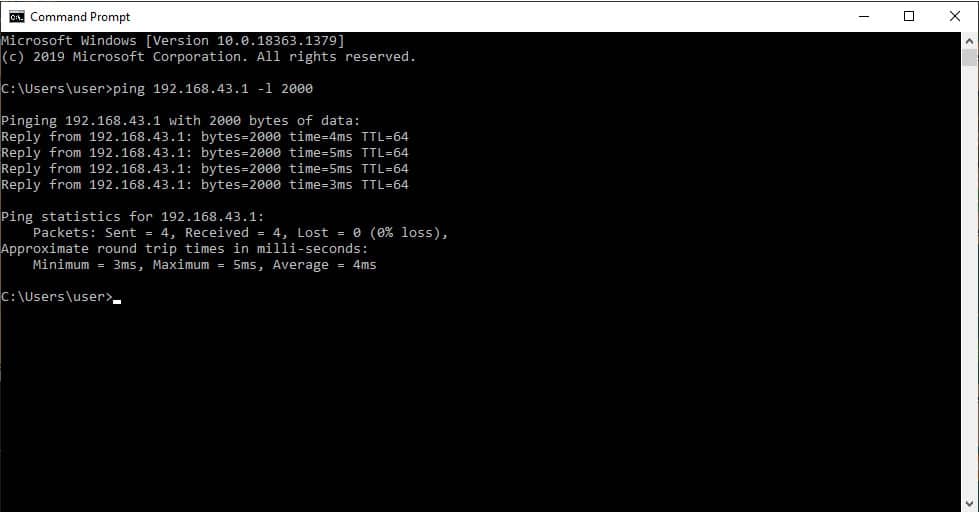
In the screenshot in Figure 1.0 above, you can see that we are sending an ICMP packet size of 2000 bytes to a gateway with the IP 192.168.43.1. The packet size of 2000 bytes is generally larger than most MTU in a typical ethernet network. As you can see, the packet successfully went through the path and reached its destination because it is being fragmented by the routers along the path.
Step 2: Now, set the “Don’t Fragment” flag using the command below, and let’s see what happens: ping 192.168.43.1 -f -l 2000.
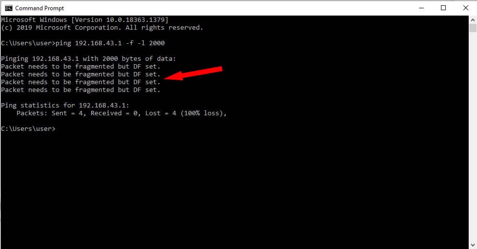
As you can see from the screenshot in Figure 2.0 above, the destination device returns a message that says: “Packet needs to be fragmented but DF set”. Since we chose not to fragment packets, all the routers along the path will have no choice but to drop the packet.
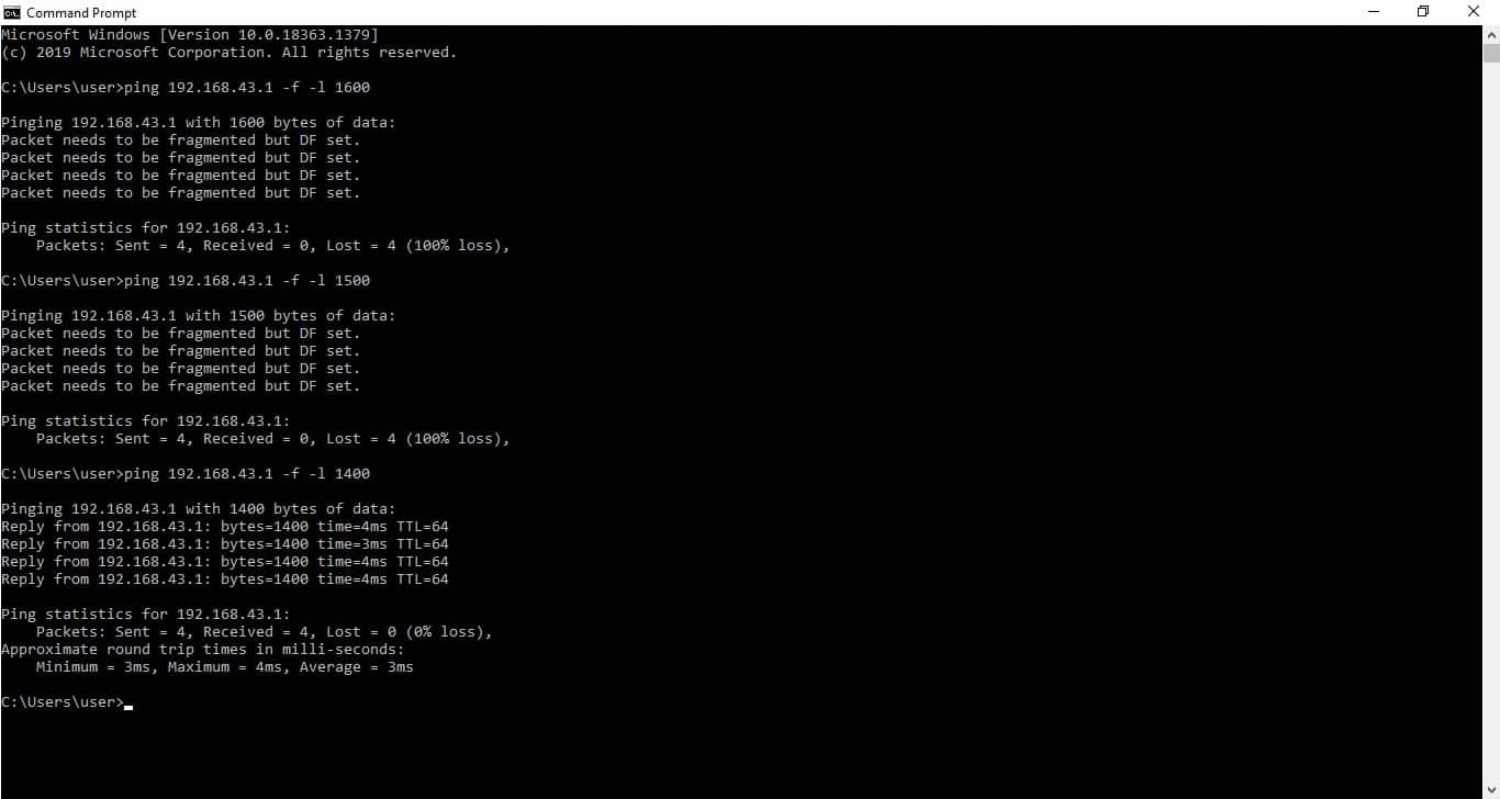
Step 3: Repeat the above process and keep adjusting the packet size until you find the path MTU. In the screenshot in Figure 3.0 above, we started with 1700 bytes and moved down in steps of 100 bytes until we got a successful ping reply. That means the path MTU between our source and destination is somewhere between 1400 and 1500 bytes.

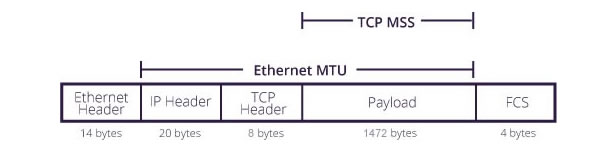
Step 4: The next step would be to move the size up and down in steps of 10 and 1 as shown in Figure 4.0 above until we figure out the right MTU size. We’re basically looking for the largest packet size that won’t return an error. This finally led us to a packet size of 1472 bytes. As you can see, a packet size of 1473 was too large, but 1472 bytes happens to be the ideal packet size. The packet size of 1472 represents the payload size or Maximum Segment Size (MSS) as shown in Figure 5.0 below.
Conclusion
In conclusion, please note that the actual MTU size includes the size of the TCP and IP headers, which can range between 20 and 60 bytes in total, depending on the transmission media. For our transmission media, the TCP and IP headers make up a total of 28 bytes (8 bytes + 20 bytes). Therefore, 1472 bytes + 28 bytes gives us the actual MTU size, which is 1500 bytes. This is typically the MTU size allowed by most Ethernet networks at the network layer.
MTU FAQs
What is MTU in ping?
MTU stands for Maximum Transmission Unit. This is the maximum length of a packet that a switch or a router can handle. The sender of a packet checks the MTU of the receiver and will then break up its packets if they are longer than that maximum, so your transmission travels in twice the number of packets than it needed to. More packets take longer to process and have to be reassembled at the receiving end, so, getting MTU mismatches on a route will slow down transmission times.
How MTU is calculated?
Confusingly, different systems have different definitions of what is included in an MTU calculation. On a private network, the standard MTU is 1500 bytes. This is the contents of a frame and doesn’t include the frame header or frame checksum (FCS). The Ethernet MTU does include the TCP/IP header within those frame header and tail. Ping will pack out the contents of a packet to a given length and then add on the TCP/IP headers. This data payload length is really what is known as the segment size, so you can work out the maximum segment size (MSS) with Ping. As the standard IP header length is 20 bytes and the TCP header is 8 bytes long, you can expect that the maximum acceptable length that you discover with Ping is 28 bytes shorter than the actual packet size. So, if you deduce with Ping an MSS of 1482 bytes, you have an MTU of 1500 bytes.
How do I ping MTU 9000?
To check whether a route will take a packet that is 9000 bytes in length, you need to issue a Ping command that forbids fragmentation and packs out the data payload. That payload length should be 8972 bytes. When the packet headers are added on (28 bytes), the total length of the packet that Ping will send will be 9000 bytes. So, issue the command:
ping <destination address> -f -l 8972
Substitute the IP address or domain name of the target for <destination address>.

Thank you for the article, it was helpful.
Note however, the last two paragraphs use “bits” whereas it should be “bytes”, so quite wrong on that aspect.
Well spotted and thank you – fixed!
Does someone know, why I can PING until -f -l 8972 without error if my NIC says MTU/Jumbo Frame is set to 9014? Should it not be 8986 (assuming the mentioned 28 bits are correct)?
You may need to look into any additional network introduced overhead (beyond the 28 bytes). Check your NIC configuration with ipconfig.
Brilliant article written in nice simple terms….great work…thank you.
Sorry for coming late to the party, but from the paragraph “How MTU is calculated?” on, if you write “bits” you really mean “bytes”. Otherwise, profoundly and clearly written, thanks.
Thanks! Fixed
Great explanation! In the section How is MTU calculated “TCP header is 8 bits long, you can expect that the maximum acceptable length that you discover with Ping is 28 bits shorter than the actual packet size. So, if you deduce with Ping an MSS of 1482, you have an MTU of 1500.” You have a typo, it should be 1472. 1472+28=1500
So I got 1402 and bumped it up to 1409 which is the max can can go without errors so should I add 28 to it and put it in my router mtu settings?
This may help, as long as it doesn’t exceed the limitations of other devices (routers, switches, etc.) on your network.
Ping actually gives you the MSS (max segment size) not MTU. MTU is simply things others than ethernet stuff. MSS = MTU – (IP+ TCP/UDP)